ORIGINAL RESEARCH

Planning orthodontic frontal teeth inclination and estimating bone thickness from cone-beam computed tomography images

Kopetskiy IS1, Meskhiya NG1, Kopetskaya AI1, Eremin DA1, Orekhova DD2
About authors

1 Pirogov Russian National Research Medical University, Moscow, Russia

2 Lomonosov Moscow State University, Moscow, Russia

Correspondence should be addressed: Nana G. Meskhiya
Ostrovityanova, 1, Moscow, 117997; moc.liamg@aklepilin

About paper

Author contribution: Kopetskiy IS analyzed the literature; Meskhiya NG conducted the study, gathered and analyzed clinical data; Kopetskaya AI processed and analyzed source medical records; Eremin DA, Orekhova DD performed data analysis.

Compliance with ethical standards: the study was approved by the Ethics Committee of Piragov Russian National Research Medical University (Protocol No.116 dated March 26, 2012); informed consent was obtained from all study participants or their legal representatives.
Received: 2021-03-16 Accepted: 2021-04-05 Published online: 2021-04-27
|
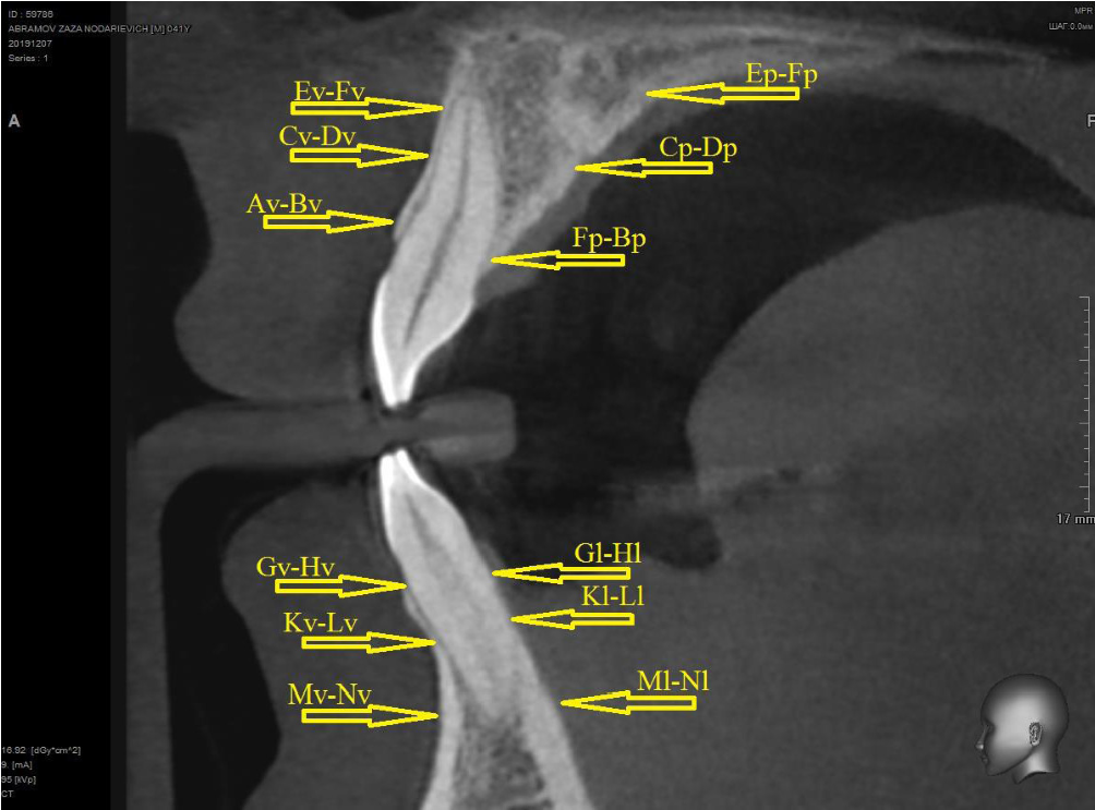
Fig. 1. Measurements on the upper and lower jaws
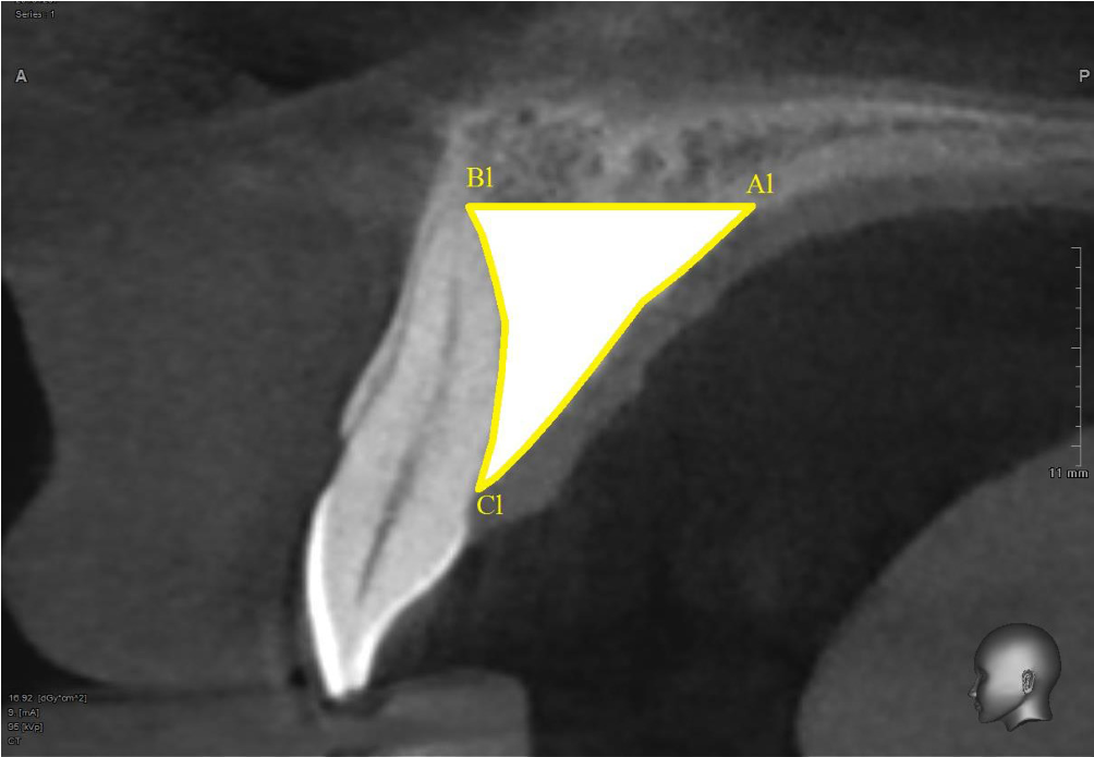
Fig. 2. Bone tissue area measurement
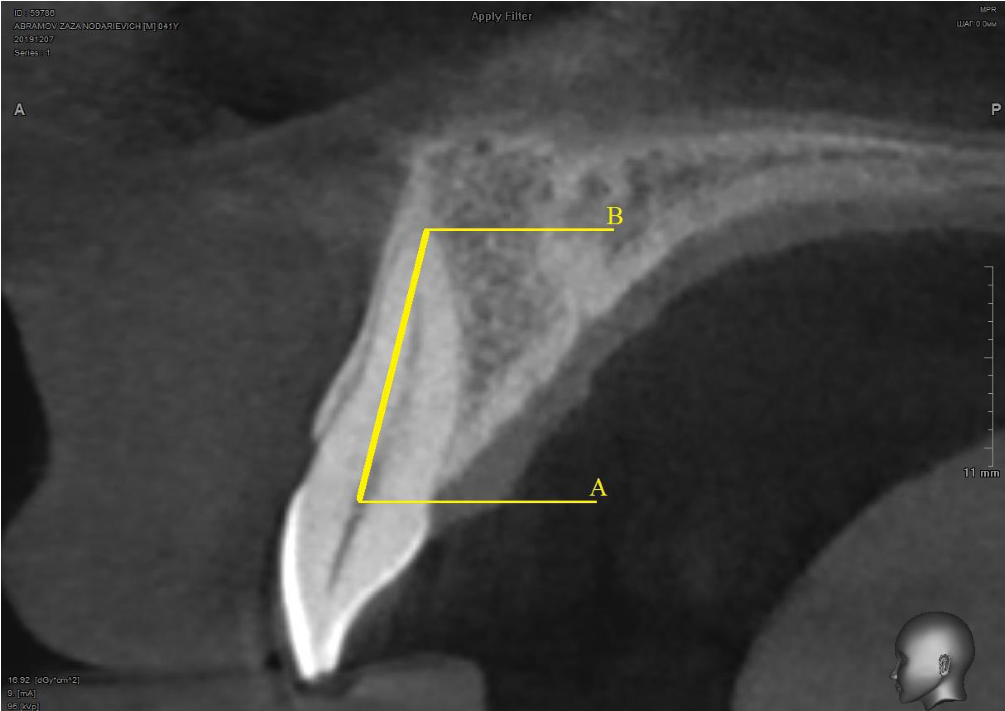
Fig. 3. Root-length measurement
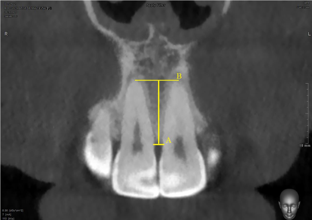
Fig. 4. Measurement of interdental septum height
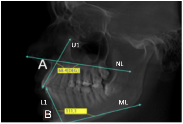
Fig. 5. Measurement of mandibular and maxillary incisor inclination
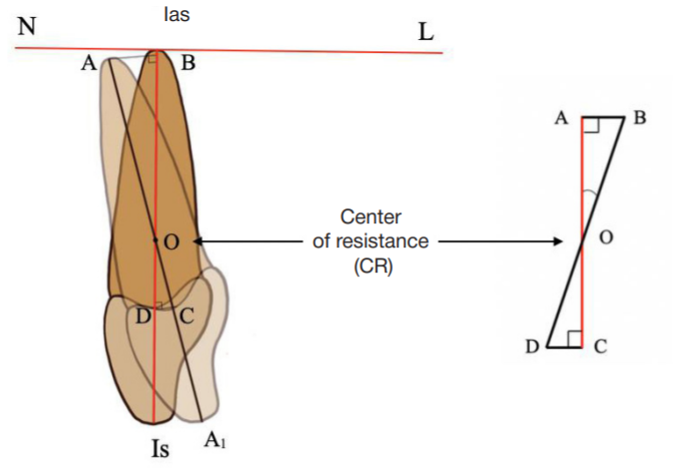
Fig. 6. The schematic representation of maxillary linear tooth movement in the surrounding bone tissue in the event of retrusion. Is is the cutting edge of the maxillary incisor; Ias is the apex of the maxillary incisor; Ias–Is is the incisor long axis; NL is a line in the maxillary plane; ∠Is–Ias–NL is the angle of maxillary incisor inclination; BD is a long tooth axis in the event of a normal (standard) incisor position; AA1 is the long axis of a retruded incisor (actual position); O is the center of resistance; ∠BOA is an angle between the normal (standard) and actual axes; ∠COD is an angle between the normal (standard) and actual axes; AC means that the line BA is perpendicular to the line AC; ∠ Is–Ias –L (∠Is–Ias to NL) is an angle that characterizes the normal position of the incisor relative to the maxillary plane NL; Ias–Is is the long axis of a normally positioned (inclined) incisor; AA1 is the long axis of a retruded incisor; point B is the projection of the apical point A of a retruded maxillary incisor to the axis of a normally inclined tooth; point D is the projection of the deepest point of the cementoenamel junction in the upper cervical region of the root of a retruded incisor to the long axis 12 of a normally inclined incisor; point С is a point in which the perpendicular drawn from the deepest point of the cementoenamel junction in the upper cervical region of a retruded tooth to the tooth axis of a normally inclined incisor and the line AA 1; O is the center of resistance; ∠BOA = ∠COD is an angle between the normal (standard) and actual axes; triangles АОВ and СОD are right-angled triangles
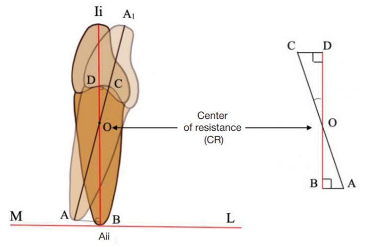
Fig. 7. Schematic representation of mandibular incisor retrusion
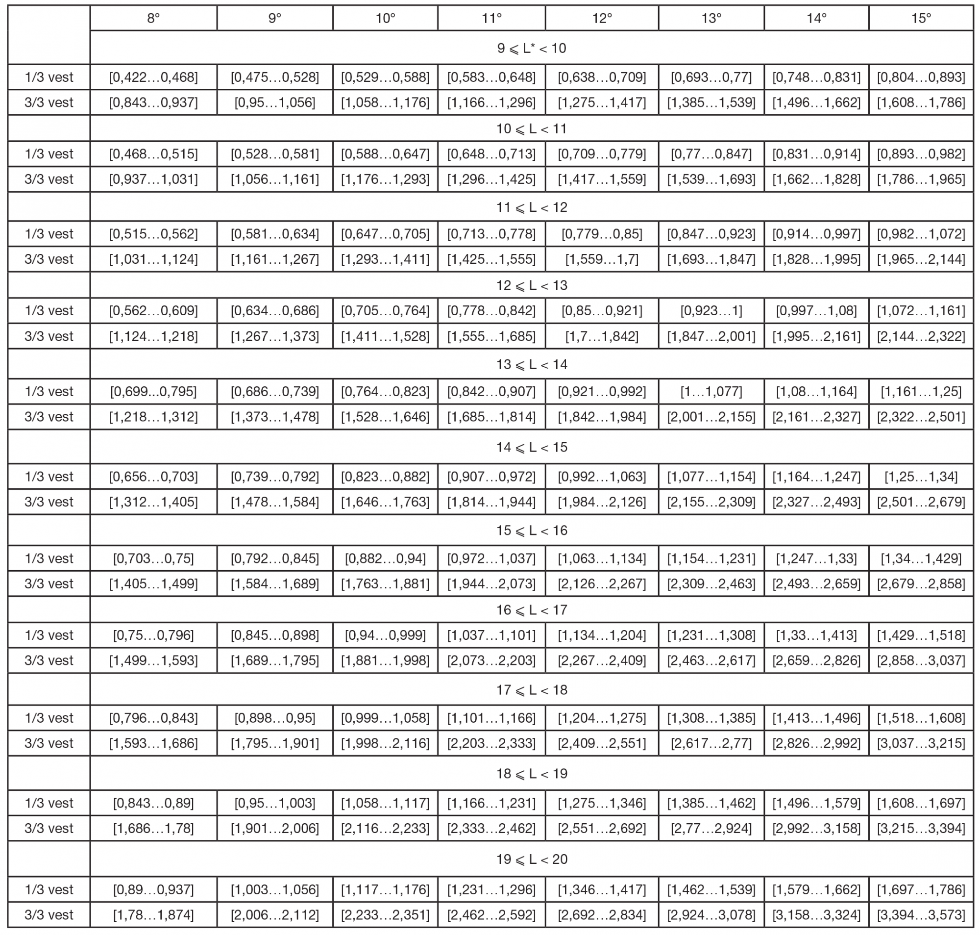
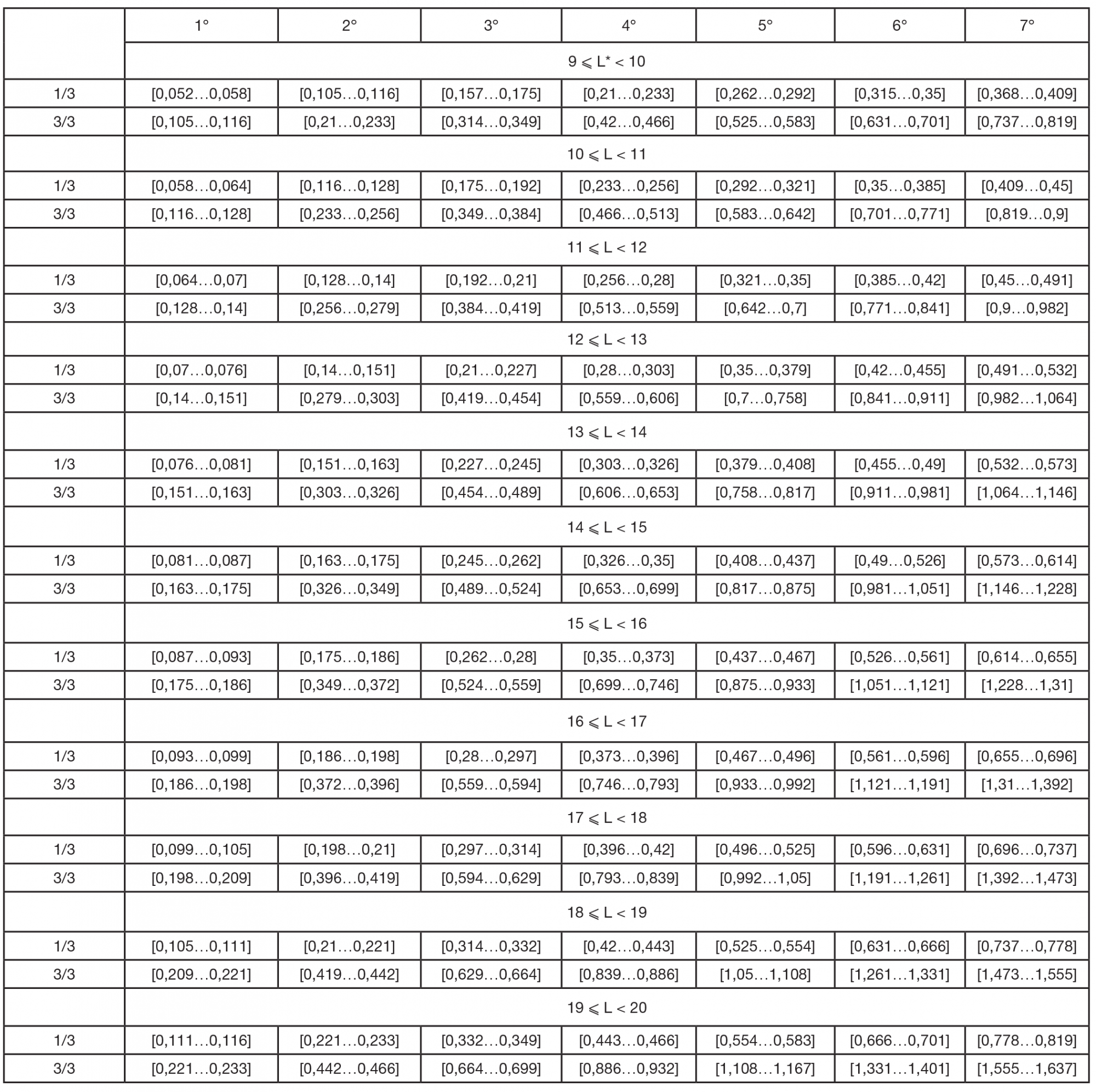
Table 1. The universal table of linear tooth movement in the bone (mm) depending on tooth inclination (degrees)
Note: L is root length.
Table 2. The universal table of linear tooth movement in the bone (mm) depending on tooth inclination (degrees)
Table 3. Comparison of alveolar bone parameters surrounding the tooth 3.3. in the events of its protrusion and retrusion
Note: BT stands for bone thickness; p < 0.05 indicates statistically significant differences.