ORIGINAL RESEARCH

Study of the human brain potentials variability effects in P300 based brain–computer interface

About authors

Lomonosov Moscow State University, Moscow, Russia

Correspondence should be addressed: Ilya P. Ganin
Leninskie Gory, 1, str. 12, k. 246, Moscow, 119234, Russia; ur.liam@ninagpi

About paper

Funding: the study was funded by the Russian Science Foundation, project number 21-75-00021, https://rscf.ru/project/21-75-00021/

Author contribution: Ganin IP — research, data analysis and interpretation, literature analysis, preparation of the text; Kaplan AYa — data interpretation.

Compliance with ethical standards: the study was approved by Ethical Review Board at the Lomonosov Moscow State University (protocol number 2 of 11 October 2010) and carried out using EEG data (http://brain.bio.msu.ru/eeg_mov_matrix_BCI.htm) obtained by the authors and published earlier (https://doi.org/10.1016/j.neulet.2011.03.089).
Received: 2022-05-04 Accepted: 2022-05-29 Published online: 2022-06-21
|
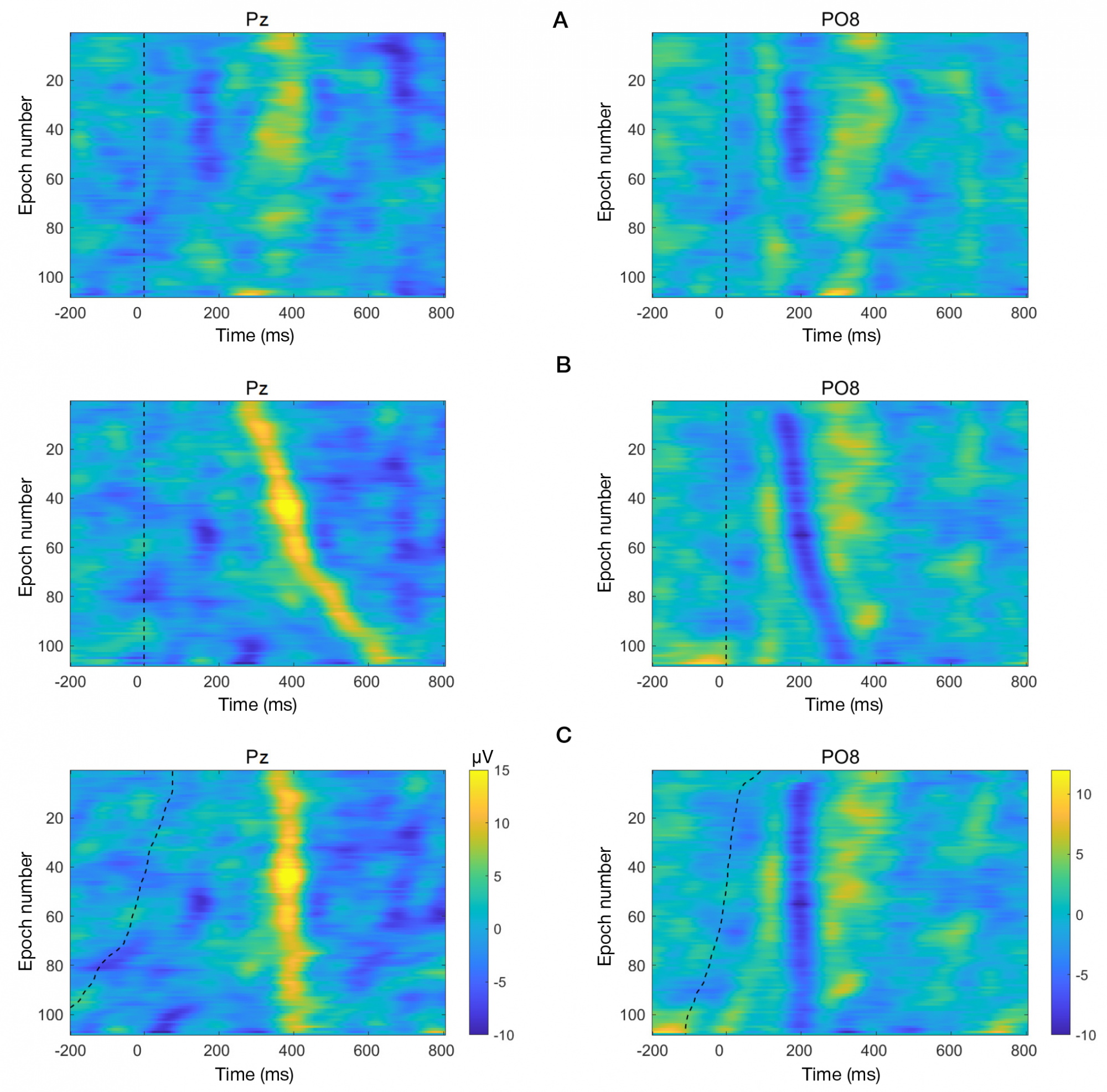
Fig. 1. Color maps of single target EEG epochs for subject #1, 'static matrix' mode, leads Pz and PO8. Horizontal axis represents time, ms; vertical axis represents individual epochs numbered and sorted by the number from top to bottom, with the moving average-based vertical smoothing applied in series of 10. A. The epochs are sorted in chronological order (as recorded). B. The epochs are sorted by peak latency for P300 (Pz) or N1 (PO8). In charts A and B the epochs are synchronized by the moment of stimulus presentation (vertical dashed lines). C. Peak latency-corrected epochs with dashed lines indicating the moment of stimulus presentation
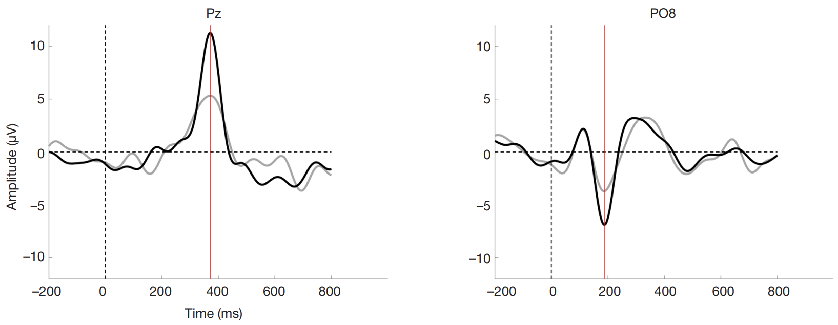
Fig. 2. An example of averaged target ERP (subject #1) acquired in the 'static matrix' mode. Gray curves correspond to standard method of ERP averaging (no latency correction applied), black curves correspond to the use of peak latency-corrected epochs for P300 (Pz) and N1 (PO8). Vertical dashed lines (0 ms) indicate the moment of stimulus presentation; red lines indicate the latency of particular component in a given lead
Fig. 3. The amplitudes of P300 and N1 components (by modulus) for different modes, calculated by the standard method (no latency correction applied) as opposed to the use of peak latency-corrected epochs for P300 (Pz, right chart) and N1 (left chart). Heights and error bars correspond to means and standard errors of the mean, respectively (n = 12)
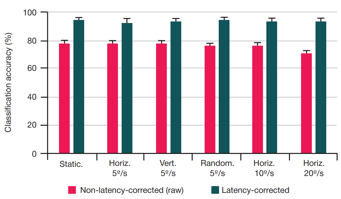
Fig. 4. The offline classification accuracy for different modes, calculated by the standard method (no latency correction applied) as opposed to the use of peak latency corrected epochs for P300 and N1. Heights and error bars correspond to means and standard errors of the mean, respectively (n = 12)